A slip ring is a vital
electromechanical device that enables the transfer of
power and electrical signals from a stationary platform to a rotating
structure. A slip ring can be used in any electromechanical
system or machine/equipment that requires rotation while transmitting
the power or signals, such as those found in radar antenna, gun turrets, periscopes, electro-optic sensor gimbals, space satellites,
and etc. Slip ring can excellently improve inside the system
the mechanical performance, simplify
system operation and eliminate damage-prone wires dangling
from movable joints.
The slip ring is also called rotating
electrical connectors, rotary electrical interfaces,
swivels, collectors, or electrical rotary joints, these
rings are commonly found in slip ring motors, electrical
generators for alternating current (AC) systems and
alternators and in packaging machinery, cable reels, and
wind turbines. It has become a commonplace component in many of today’s industrial, military and even everyday equipment/machine, where they play a crucial role. They can be used on any rotating object to
transmit power, control circuits, or analog or
digital signals including data such as those found on
aerodrome beacons, rotating tanks, power shovels, radio
telescopes or heliostats.
|
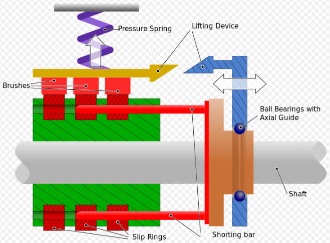 |
Sketch
of a cross-section of slip rings for an electric
motor. In this example, the slip rings have a
brush-lifting device and a sliding contact bar,
allowing the slip-rings to be short-circuited when
no longer required. This can be used in starting a
slip-ring induction motor, for example. |
A slip ring (in electrical engineering terms) is a method of
making an electrical connection through a rotating assembly.
Formally, it is an electric transmission device that allows
energy flow between two electrical rotating parts, such as
in a motor. Slip rings handle either power, data or both across a number of rings on which a spring or other loaded contact finger, ring or brush is held in place to pass power as the rings rotate.
The power levels range from milliwatts to hundreds of kilowatts dependent on
the real application. In all applications, frictional wearing is the main determinant of the lifecycle of the slip ring.
Slip ring products can be designed in a variety of configurations. For example they can provide an open through-bore to accommodate other components such as a fluid joint or a wave guide. Instead of a drum the rings can be configured in a platter or pancake. This is appropriate if the space available for the slip ring is short and wide instead of tall and narrow.
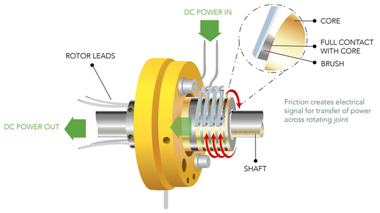
Typically, slip ring is constituted by a stationary graphite or
metal contact (brush) which rubs on the outside diameter of
a rotating metal ring. At a very elementary level, a slip ring is comprised of two major components – a metal brush, and a metal ring. The “brush” can look like a brush made from metal fibers, but more often it looks like a single wire or a spring with a pad of material affixed to the end that contacts the ring. As the metal ring turns, the electric
current or signal is conducted through the stationary brush
to the metal ring making the connection. Additional
ring/brush assemblies are stacked along the rotating axis if
more than one electrical circuit is needed. Either the
brushes or the rings are stationary and the other component
rotates. This simple design has been used for decades
as a rudimentary method of passing current into a rotating
device.
The ring itself is a band of electrically conductive material, mounted on a shaft. Although it’s insulated from the shaft itself, the slip ring is connected to the rotor or rotating assembly through windings or other electrical connections.
The outer part of this slip ring remains in continuous sliding contact with the stationary brushes – or other stationary conductors – which provides either intermittent or continuous rotating devices with unbroken contact between the rotating assembly and external circuit. This ensures power and data are able to be transmitted at all times.
Both this ring and the brush are contained within a single housing, designed to protect the working parts from harmful environmental factors such as dust and moisture.
|
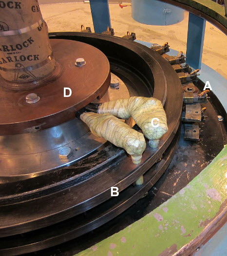 |
Slip rings on a hydroelectric generator; A - stationary spring-loaded graphite brushes, B - rotating steel contact ring, C - insulated connections to generator field winding, D - top end of generator shaft. |
A critical aspect of slip ring design is the materials used to make the rings and the brushes. After World War II
slip ring
suppliers and manufacturers responded to requirements from the emerging electronics industry with gold plated rings using gold wire brushes. Up until the 1970’s many slip rings used copper rings and graphite brushes. Copper is smooth and conducts electricity well. Graphite conducts well, it is soft, and it does not abrade the copper rings. But for advanced applications such as space satellites and missiles, graphite brushes were inadequate. There was a burst of research and invention in the early years of the space program to address emerging needs, mostly in space and missile programs, that produced advanced gold on gold alloy systems and systems that employed silver alloy rings with brush tips made from silver graphite mixtures. Today these two systems, gold-on-gold and silver/silver-graphite, are the mainstays of the slip ring industry. Gold-on-gold systems are often used for low current signal circuits because they are compact. Silver/Silver-graphite systems are often selected
by
manufacturer of slip rings for higher current power circuits because in these applications they are more economical, and have long service life.
Some other names used for slip ring are collector ring,
rotary electrical contact and electrical slip ring. Some
people also use the term commutator; however, commutators
are somewhat different and are specialized for use on DC
motors and generators. While commutators are segmented, slip
rings are continuous, and the terms are not interchangeable.
Rotary transformers are often used instead of slip rings in
high-speed or low-friction environments.
A slip ring can be used within a rotary union to function
concurrently with the device, commonly referred to as a
rotary joint. Slip rings do the same for electrical power
and signal that rotary unions do for fluid media. They are
often integrated into rotary unions to send power and data
to and from rotating machinery in conjunction with the media
that the rotary union provides.
Slip rings are made in various types and sizes by
slip ring
designer and product developer; one device
made for theatrical stage lighting, for example, had 100
conductors. The slip ring allows for unlimited
rotations of the connected object, whereas a slack cable can
only be twisted a few times before it fails.
The slip
ring engineer should be given the maximum
space available in the system so all existing
candidate designs can be considered. It is
imperative that the space required for the slip
ring be specified in the early stages of the
system design and that it be consistent with
the structural and electrical demands.
Wireless and contactless slip rings do not rely on the typical friction
based metal and carbon brush contact methods that have been
employed by slip rings since their invention, such as those
explored above. Instead, they transfer both power and data
wirelessly via an electromagnetic field, which is created by
the coils that are placed in the rotating receiver, and the
stationary transmitter. Wireless slip rings are
considered an upgrade from - or alternative to - traditional
slip rings, as their lack of standard mechanical rotating
parts means they're typically more resilient in harsh
operating environments, and require less maintenance and
upkeep. Contactless, wireless slip rings are the next generation in inductive power transfer solutions, specifically designed to replace existing, aging mechanical slip ring technology. Moving on from a reliance on friction based metal and carbon brush contact to enable the transfer of power and data, wireless slip rings utilize IPT to transfer power via an electromagnetic field created by coils placed in the stationary transmitter and rotating receiver. By removing the inherent need for friction or contact to generate an electrical current, wireless slip rings significantly reduce the maintenance costs associated with worn mechanical slip rings, while also offering a simple, clean design that’s easily integrated into any application or device.
Today’s slip rings are reliable, have long service life and can be designed for extraordinary environments, including the vacuum of space, the shock of a tank gun turret or the vibration of a helicopter rotor.
Defining System Interface
Requirements
The slip ring engineer will need to know these
system interface considerations:
1. Can the slip ring mount directly on the
center line or is a through-bore required in
the slip ring? A through-bore can be used
to mount the slip ring on a shaft or used for
routing hydraulic lines, pneumatic lines, fiber
optic rotary joint, wave guide. etc.
2. How will the slip ring attach to the system?
A slip ring must be mounted with a flexible
coupling on one side of the unit. Hard
mounting on both the rotor and stator will
cause the slip ring to fail prematurely by
translating system load into the slip ring
bearing structure.
3. How should the electrical connections to
the slip ring be made? Is it desirable to have
connectors integral with the slip ring on both
the rotor and stator, or would flying leads on
one or the other ends be desirable? And if
flying leads are preferred, should they exit the
rotor / stator in a radial or axial direction, and
what length should the leads be?
Defining Electrical
Requirements
The specified current enables the slip ring engineer to
propose a unit with the appropriate cross-sectional area of
the rings, brushes and lead wires. The specified voltage
dictates the spacing between adjacent rings and brushes. It
is helpful in achieving the most cost effective and smallest
practical envelope not to rate all circuits at the maximum
level. For example, if you need 20 circuits total, three of
which must carry ten amps, designate three for high current.
Don’t insist on 100% functional interchangeability by
specifying that all 20 circuits carry ten amps. And, if ten
amps is a surge current with a continuous current of only
two amps, tell us that, too. There is no reason for you to
pay for ten amps continuous capacity when you only need two
amps. Be aware that voltage surges and spikes are the major
cause of system slip ring failures. A conservative approach
can be used to circuit design, however, it is not uncommon
in some power supply systems to see voltage spikes ten or
more times the normal operating voltage. We strongly
recommend surge protection on all power supplies. Most
smaller slip rings will satisfactorily conduct signals to 50
megabits / sec. Special slip rings can be used to pass
broadband signals from DC to 1 gigahertz and data rates of
500 megabits or even higher. Cross-talk, insertion loss and
bit error rate information can be projected, if tested for
actual values, when data rates, formats and impedances are
defined. The appropriate shielding techniques will be
incorporated to meet the system requirements.
Defining Mechanical
Requirements
1. Operating speed (rpm) is an important design parameter.
Almost any slip ring can operate successfully at speeds to
100 rpm although many applications only require operation at
a few rpm. Slip rings are routinely used to instrument test
jet turbine engines operating at speeds in excess of 20,000
rpm. The operating speed, in conjunction with the diameter,
dictates the surface speed of the ring relative to the brush
and hence the internal design approach and material
selection. 2. What rotational life is necessary for your
application? Will the unit oscillate or rotate at a
continuous speed?
The environment in which the slip ring must
survive is a key factor. Operating temperature
range is important in specifying the proper
lubricant. And if the slip ring will operate
exposed to the elements or to a hostile
environment, integral seals must be included
in the design. Any unusual shock or vibration
should also be specified. Where are slip rings most
commonly found?
Slip rings are utilized in a variety of devices across a
broad range of industries. Slip rings are used in systems
that require continuous rotation while transmitting power
and data from a stationary unit to a rotating device. Some of the
slip ring applications include:
TRUCKS & MAN LIFT EQUIPMENT:
Aerial Work Platforms
Bridge Cranes
Platform Cranes
INDUSTRIAL/COMMERCIAL IN-PLANT
EQUIPMENT:
Automated Welding Equipment
Centrifuges
Conveyor Systems
Custom Machinery
Fabrication Equipment
DRILLING & OTHER BORING
EQUIPMENT:
Off-Shore Drilling Rigs
Down hole Drill and Geotechnical Testing
Horizontal Earth Boring & Drilling
SIGNAGE RELATED EQUIPMENT:
Advertising Displays
Exhibits and Displays
MISC. OFF-HIGHWAY HEAVY
EQUIPMENT:
Forklifts
Utility Trucks
Truck Body / Service Cranes
MILITARY PURPOSE
Slip rings have been widely used for military purpose to
meet the demand of various applications.
The increasing complexity of modern military vehicles
demands slip rings to provide reliable electrical interfaces
between the stationary and rotating parts of these vehicles.
Today’s rotorcraft applications place unique demands on slip ring technology because of equipment requirements
and environmental conditions. From de-ice applications (with their need for high rotational speed, exposure to
weather conditions and high vibration) to weapon stations and electro-optic sensor systems (with high bandwidth
signal transmission), helicopter slip rings must perform in a highly reliable mode with the latest product
advancements.
OTHER:
Amusement Rides
Arcade Machines
Unmanned Vehicles
Remotely Operated Vehicles
Car Wash Equipment
Wind Turbines
Commercial Camera
Medical Device
Security Systems
A slip ring is an
electromechanical device that allows the transmission of
power and electrical signals from a stationary to a rotating
structure. Also called a rotary electrical joint, collector
or electric swivel, a slip ring can be used in any
electromechanical system that requires unrestrained,
intermittent or continuous rotation while transmitting power
and / or data. It can improve mechanical performance,
simplify system operation and eliminate damage-prone wires
dangling from movable joints. For high speed data transfer
or for data transfer in EMI sensitive environments, Fiber
Optic Rotary Joints (FORJ’s) can be used. Fiber Optic Rotary Joints (FORJs) are to optical signals what electrical slip rings are to electrical signals, a means to pass signals
across rotating interfaces, particularly when transmitting large amounts of data. FORJs maintain the intrinsic advantages of fiber
end to end.
China truesci supply high-quality slip ring products used in critical defense and space applications. |